Electrical Engineering Stack Circuit Diagram
Electrical Engineering Stack Circuit Diagram Introduction A voltage divider is a simple circuit which turns a large voltage into a smaller one. Using just two series resistors and an input voltage, we can create an output voltage that is a fraction of the input. Voltage dividers are one of the most fundamental circuits in electronics. If learning Ohm's law was like being introduced to the ABC's, learning about voltage dividers would be

Simple Voltage Divider: When building a circuit, there may come a time when you only need a fraction of the voltage that is in the input. Dividing this voltage is simple and requires a few basic components. You are going to need two resistors of the same value, and …
How to Make a Voltage Divider Circuit: 9 Steps (with Pictures) Circuit Diagram
Through this technique, you can take any voltage and lower it to any level you want. How to Reduce Voltage in Half To reduce voltage in half, we simply form a voltage divider circuit between 2 resistors of equal value (for example, 2 10KΩ) resistors.

Let's make a simple voltage divider together :)If you want to know how to make a voltage divider, this is the video for you. No one can put it simpler than t

Voltage Divider Tutorial For Beginners Circuit Diagram
Yo! friends welcome back to my channel so quick one, I'll be showing you how u can use a resistor to a simple voltage divider at home ..let's dive in guys.# Voltage Divider Rule The simplest, easiest to understand, and most basic form of a passive voltage divider network is that of two resistors connected together in series. This basic combination allows us to use the Voltage Divider Rule to calculate the voltage drops across each series resistor.
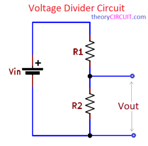
As you work with different types of circuits requiring a voltage divider, the schematic to the right can help you develop different output voltages for this application. The equation Vout = Vin * (R2 / (R2 + R1)) is the equation describing how the output voltage is related to the input voltage in this type of circuit. Voltage divider circuit : How to build a simple voltage divider using resistors or a potentiometer.
![Design a resistor voltage divider [Step by step 2025] Circuit Diagram](https://www.yamanelectronics.com/wp-content/uploads/2022/11/resistor-voltage-divider-circuit-example-1024x564.png)